Wednesday, July 20, 2011

Catalysis

Catalysis is an action by catalyst which takes part in a chemical reaction process and can alter the rate of reactions, and yet itself will return to its original form without being consumed or destroyed at the end of the reactions. This definition is one of many definitions about catalysis.

Three key aspects of catalyst action:
1. Taking part in the reaction
     It will change itself during the process by interacting with other reactant/product molecules
2. Altering the rates of reactions
     In most cases the rates of reactions are increased by the action of catalysts; however, in some
     situations the rates of undesired reactions are selectively suppressed
3. Returning to its original form
     • After reaction cycles a catalyst with exactly the same nature is ‘reborn’
     • In practice a catalyst has its lifespan - it deactivates gradually during use


Already from these definitions, it is clear that there is a direct link between chemical kinetics and catalysis, as according to the very definition of catalysis it is a kinetic process. There are different views, however, on the interrelation between kinetics and catalysis. While some authors state that catalysis is a part of kinetics, others treat kinetics as a part of a broader phenomenon of catalysis.

Despite the fact that catalysis is a kinetic phenomenon, there are quite many issues in catalysis which are not related to kinetics. Mechanisms of catalytic reactions, elementary reactions, surface reactivity, adsorption of reactants on the solid surfaces, synthesis and structure of solid materials, enzymes, or organometallic complexes, not to mention engineering aspects of catalysis are obviously outside the scope of chemical kinetics.

Some discrepancy exists whether chemical kinetics includes also the mechanisms of reactions. In fact if reaction mechanisms are included in the definition of catalytic kinetics it will be an unnecessary generalization, as catalysis should cover mechanisms.

Catalysis is of crucial importance for the chemical industry, the number of catalysts applied in industry is very large and catalysts come in many different forms, from heterogeneous catalysts in the form of porous solids to homogeneous catalysts dissolved in the liquid reaction mixture to biological catalysts in the form of enzymes. Catalysis is a multidisciplinary field requiring efforts of specialists in different fields of chemistry, physics and biology to work together to achive the goals set by the mankind. Knowledge of inorganic, organometallic, organic chemistry, materials and surface science, solid state physics, spectroscopy, reaction engineering, and enzymology is required for the advancements of the discipline of catalysis.

Catalyst

Facts and figures about catalysts :
   a. Life cycle on the earth :       - Catalysts (enzyme) participates most part of life cycle, e.g. forming, growing and decaying
      - Catalysis contributes great part in the processes of converting sun energy to various other
           forms of energies, e.g. photosynthesis by plant CO2 + H2 C + O2
      - Catalysis plays a key role in maintaining our environment
  b. Chemical industry
       - ca. $2 bn annual sale of catalysts
       - ca. $200 bn annual sale of the chemicals that are related products
       - 90% of chemical industry has catalysis-related processes
       - Catalysts contributes ca. 2% of total investment in a chemical process
                                                                                                                    (Erzeng Xue, 2003)

So?! What is catalyst???
A catalyst was defined by Ostwald as a compound, which increases the rate of a chemical reaction, but which is not consumed by the reaction. This definition allows for the possibility that small amounts of the catalyst are lost in the reaction or that the catalytic activity is slowly lost. Lets take a look for the example of a catalytic reaction between two molecules A and B with the involvment of a catalyst. From the figure below, we can see that the catalyst unaltered and ready for taking part in a next catalytic cycle after forming the products.


In order to understand how a catalyst can accelerate a reaction, a potential energy diagram should be considered.


The figure above represents a concept for a non-catalytic reaction of Arrhenius, who suggested that reactions should overcome a certain barrier before a reaction can proceed. For catalytic reaction (reaction with catalyst), the change in the Gibbs free energy between the reactants and the products ΔG does not change in case of a catalytic reaction, however the catalyst provides an alternative path for the reaction. See the figure below.

                                                                        (Dmitry Murzin, 2005).


The action of catalyst :
1. Catalyst action leads to the rate of a reaction to change
     - Forming complex with reactants/products, controlling the rate of elementary steps in the process.
       This is evidenced by the facts that :
            a. The reaction activation energy is altered
            b. The intermediates formed are different from those formed in non-catalytic reaction
            c. The rates of reactions are altered (both desired and undesired ones)
    - Reactions proceed under less demanding conditions
       Allow reactions occur under a milder conditions, e.g. at lower temperatures for those heat
          sensitive materials

2. The use of catalyst does not vary ΔG & Keq values of the reaction concerned, it merely change
      the pace of the process
      - Whether a reaction can proceed or not and to what extent a reaction can proceed is solely
          determined by the reaction thermodynamics, which is governed by the values of ΔG & Keq,
          not by the presence of catalysts
    - In another word, the reaction thermodynamics provide the driving force for a rxn; the presence
         of catalysts changes the way how driving force acts on that process.
         e.g CH4(g) + CO2(g) = 2CO(g) + 2H2(g)   ΔG°373=151 kJ/mol (100 °C)
                                                                             ΔG°973 =-16 kJ/mol (700 °C)
        a. At 100°C, ΔG°373=151 kJ/mol > 0. There is no thermodynamic driving force, the reaction
             won’t proceed with or without a catalyst
       b. At 700°C, ΔG°373= -16 kJ/mol < 0. The thermodynamic driving force is there. However,
             simply putting CH4 and CO2 together in a reactor does not mean they will react. Without a
             proper catalyst heating the mixture in reactor results no conversion of CH4 and CO2 at all.
            When Pt/ZrO2 or Ni/Al2O3 is present in the reactor at the same temperature, equilibrium
             conversion can be achieved (<100%).

                                                                                                                            (Erzeng Xue, 2003)

Catalysts classification :

1. Based on the its physical state, a catalyst can be :
     a. Gas
     b. Liquid
     c. Solid
2. Based on the substances from which a catalyst is made
     a. Inorganic (gases, metals, metal oxides, inorganic acids, bases, etc.)
     b. Organic (organic acids, enzymes, etc.)
3. Based on the ways catalysts work
     a. Homogeneous
     b. Heterogeneous
4. Based on the catalyst’ action
     a. Acid-base catalysts
     b. Enzymatic
     c. Photocatalysis
     d. Electrocatalysis, etc.
5. According to the preparation procedure as
     a. Bulk catalysts or supports
     b. Impregnated catalysts
6. On this basis the ralative preparation methodes are:
     a. The catalytic active phase is generated as a new solid phase
     b. The active phase is introduced or fixed on a pre-existing solid by a process which intrinsically
            depends on the support surface
7. Bulk catalysts
     a. Precipitation
     b. Gelation / sol-gel
8. Supported catalysts


References : D. murzin and T. Salmi, Catalytic Kinetics, Elsivier, 2005
                    Erzeng Xue, Catalysis and Catalysts, University of Limerick, 2003


Propane

Formula                  : C3H8 
Physical Properties  : Appearance : colourless odourless gas (a small amount of an unpleasant-smelling 
                                    gas such as a thiol may be added to provide warning in the event of a leak.) 
                                 Melting point : -188 C 
                                 Boiling point : -44.5 C 
                                 Critical temperature : 96.67 C  
                                 Critical pressure : 41.94 atm 
                                 Vapour density : 1.55 
                                 Flash point : -104 C (open cup)  
                                 Explosion limits: 2.4% - 9.5 % 
                                 Autoignition temperature: 468 C

Toxicological Properties :
           • Breathing high concentrations causes a narcotic effect; however, the major property
                 is the exclusion of an adequate supply of oxygen to the lungs.
           • Hydrogen is not listed in the IARC, NTP or by OSHA as a carcinogen or potential
                carcinogen.
           • Frostbite effects are change in color of the skin to gray or white possibly followed by
                 blistering.
Reactivity Data    :  Stability : Stable
                              Incompatibility (Materials to Avoid) : Oxidizers
                              Hazardous Decomposition Products : None
                              Hazardous Polymerization : Will not occur
                              Conditions to Avoid : None

Oxygen

Formula                  : O2 
Physical Properties  : Appearance : colourless gas 
                                 Melting point : -218 C
                                 Boiling point : -183 C
                                 Vapour density : 1.11 g/l
                                 Flash point : none
                                 Explosion limits : none
                                 Autoignition temperature : none

Toxicological Properties :
         • The property is that hyperoxia which leads to pneumonia. Concentrations between
                25 and 75 molar percent present a risk of inflammation of organic matte in the body.
         • Oxygen is not listed in the LARC, NTP or by OSHA as a carcinogen or potential
                carcinogen.
         • Persons in ill health where such illness would be aggravated by exposure to
                oxygen should not be allowed to work with or handle this product.

Reactivity Data     : Stability : Stable
                              Incompatibility (Materials to Avoid) : None
                              Hazardous Decomposition Products : All flammable materials
                              Hazardous Polymerization : Will not occur
                              Conditions to Avoid : None

Methane

Formula                  : CH4
Physical Properties  : Form : colourless, odourless gas 
                                 Melting point : -182 C 
                                 Boiling point : -164 C 
                                 Water solubility : slight 
                                 Density : 0.717 g/l at 20 C 
                                 Explosion limits : 5 - 15%
Principal Hazards   : Methane is very flammable. Mixtures of methane with air are explosive within 
                                  the range 5-15% by volume of methane. 
                                 Methane can react violently or explosively with strong oxidizing agents, such as 
                                   oxygen, halogens or interhalogen compounds. 
                                 At high concentration methane acts as an asphyxiant.
Toxicological Properties :
            *  Methane is inactive biologically and essentially nontoxic; therefore, the majority is the
                   exclusion of an adequate supply of oxygen to the lungs.
            *  Methane is not listed in the IARC, NTP or by OSHA as a carcinogen or potential
                    carcinogen.
Reactivity Data       : Stability : Stable
                                Incompatibility (Materials to Avoid) : Oxidizers
                                Hazardous Decomposition Products : None
                                Hazardous Polymerization : Will not occur
                                Conditions to Avoid : None

Nitrogen

Formula                  : N2
Physical Properties  : Form : colourless gas 
                                Stability : Stable
                                Melting point : -210 C 
                                Boiling point : -195.9 C 
                                Water solubility : slight 
                                Liquid density : 0.808 g cm-3 
                                Vapour density : 1.25 g/l
Principal Hazards   : Asphyxiant at high concentrations
Toxicological Properties :
                • Nitrogen is nontoxic but the liberation of a large amount in a confined area could
                    displace the amount of oxygen in air necessary to support life.
                • Nitrogen is not listed in the LARC, NTP or by OSHA as a carcinogen or potential
                    carcinogen.
                • Persons in ill health where such illness would be aggravated by exposure to
                     nitrogen should not be allowed to work with or handle this product.
Reactivity Data      :  Stability : Stable 
                                Incompatibility (Materials to Avoid): None
                                Hazardous Decomposition Products: None
                                Hazardous Polymerization: Will not occur
                                Conditions to Avoid: None

Hydrogen

Formula                 : H2
Physical Properties : Form: colourless gas 
                                Stability: Stable, but highly flammable 
                                Melting point: -259 C 
                                Boiling point: -253 C 
                                Critical temperature: -240 C 
                                Flammability range: 4% - 75% in air

Principal Hazards    : Hydrogen is very flammable. It forms a potentially explosive mixture with air over 
                                 a wide composition range (4% - 75% hydrogen by volume).
Toxicological Properties : 
               • Hydrogen is inactive biologically and essentially nontoxic; therefore, the major property    
                    is the exclusion of an adequate supply of oxygen to the lungs.
               • Hydrogen is not listed in the IARC, NTP or by OSHA as a carcinogen or potential 
                    carcinogen.
               • Persons in ill health where such illness would be aggravated by exposure to hydrogen 
                    should not be allowed to work with or handle this product.
Reactivity Data        :  Stability : Stable
                                 Incompatibility (Materials to Avoid) : Oxidizers
                                 Hazardous Decomposition Products : None
                                 Hazardous Polymerization : Will not occur
                                 Conditions to Avoid : None

Sunday, July 3, 2011

CNT

Carbon nanotubes (CNTs) are quasi one-dimensional nanostructures with extreme mechanical characteristics and tuneable electrical properties (Loiseau A., 2006). It is a tubular form of carbon with diameter as small as 1 nm and few nm to microns of length. It can be described as a two dimensional graphene sheet rolled into a tube.

It is characterized by its Chiral Vector R (n, m) : R = n â1 + m â2,  with Ø as an angle.

With its Chiral Vector, we can classify CNTs : -  Armchair nanotube (n,m) = (5,5), Ø = 30°
                                                                       -     Zig zag nanotube (n,m) = (9,0), Ø = 0°
                                                                       -     Chiral nanotube (n,m) = (10,5), 0° < Ø < 30°


There are three tyes of CNTs :
-  Single wall CNT (SWCNT)
Consist of just one layer of carbon, greater tendency to align into ordered bundles, and used to test the theory of nanotube properties
  -  Multiple wall CNT (MWCNT)
        Consist of 2 or more layers of carbon and tend to form unordered clumps
                    -  Can be metallic or semiconducting depending on their geometry

SWCNT

MWCNT
CNT properties : 
1.       Because of C-C covalent bonding and seamless hexagonal network architecture , it becomes  the strongest and most flexible molecular material
2.      Young’s modulus of over 1 TPa vs 70 GPa for aluminium, 700 GPa for C-fiber. Strength to weight ratio 500 time ˃ for Al; similar improvements over steel and titanium; one order of magnitude improvement over graphine / epoxy
3.       Maximum strain ~ 10% much higher than any material
4.   Thermal conductivity ~ 3000 W/mK in the axial direction with small values in the radial direction
5.       Electrical conductivity six orders of magnitude higher than copper
6.       Can be metallic or semiconducting depending on chirality
-      ‘tunable “ bandgap
-  Electronic properties can be tailored through application of external magnetic field, application of mechanical deformation
7.       Very high current carrying capacity
8.    Excellent field emitter : high aspect ratio and small tip radius of curvature are ideal for field emission (Dresselhaus)
9.    Because of its special band structure, it can escape such a fate and remain conducting over lengths greater than one micron down to very low temperature (C. Dekker, 2000).

Many researches have been done for their synthesis and several methods of them are :
a.       Electric arc discharge
b.       Laser ablation
c.       Chemical vapor deposition (CVD)


CNTs Applications :
1.       Electronic devices (nanotube TV’s, nano-wiring)
2.       High strenght composites (100 times as strong as steel and 1/6 the weight)
3.       Conductive composites
4.       Medical applications (encase drug into nanotube capsule for more predictable time release)
                     5.   Catalytic application

References :  Loiseau A, Launois P, Petit P, Roche S, Salvetat JP, Understanding Carbon nanotubes from basics
                                            to applications. Springer, Lecture Notes in Physics; 2006. Vol. 677
                  M.S. Dresselhaus, G. Dresselhaus, Ph. Avouris, Topics in Applied Physics ; Carbon Nanotubes:
                                            Synthesis, Structure, Properties and Applications
                  C. Dekker, Phys. Today 52 (5) (1999) 22. See also reviews on nanotubes in Phys. World 6, 1 (2000)

MCM-41

MCM-41 (Mobil Crystalline Materials) is an amorphous silica comprising of an array of unidirectional, 2-D hexagonal mesopore structure with an extremely high surface area of ˃ 1000 m2/g-1. This mesoporous molecular sieve (M41S) was discovered by scientists of Mobil Oil Research and Development 1992. Since that, it has attracted extensive attention of researchers in academia and industry because of its large pore, large surface area, thernal stability and mild acidy property, and it has been implemented in order to increase the acidity, ion exchange capacity and specific catalytic activity of mesoporous silica molecular sieves (Hui K. S., 2006).

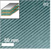
There are three different mesophases in MCM that have been identified, Lamellar (MCM-50), cubic (MCM-48), and hexagonal (MCM-41) phases. MCM-41 possesses highly regular arrays of uniform-sized channels whose diameters are in the range of 15-100 Å depending on the templates used, the addition of auxiliary organic compounds, and the reaction parameters (Xiu S. Zhao, 1996).

Cubic

Hexagonal
Lamellar

MCM-41 can be synthesized by mixing organic amine (surfactants), silica, and/or silica-alumina source to form a supersaturated solution while maintaining the mixture at a temperature between 70 and 150 °C for selected periods of time. The figure (below) shows the mechanism of liquid crystal templating via two possible pathways (Beck et al., 1992a).


The randomly ordered rodlike micelles interact with silicate species by Cou-lombic interactions in the optimal reaction mixture to produce approximately two or three monolayers of silicate encapsulation around the external surfaces of the micelles. These randomly ordered composite species spontaneously pack into a highly ordered mesoporous phase with an energetically favorable hexagonal arrangement, accompanied by silicate condensation. With the increase in heating time, he inorganic wall continues to condense (Xiu S. Zhao, 1996).

Reference : K.S. Hui, C.Y.H. Chao 2006 J. Haz. Mater. B137 1135-1148
                 Xiu S. Zhao, G.Q. (Max) Lu, and Graeme J. Millar Ind. Eng. Chem. Res. 1996, 35, 2075-2090
             George L. Athens, Ramzy M. Shayib, Bradley F. Chmelka J. Cur. Opi. Int. Sc. 14 (2009) 281-292
             Beck, J.S; Vertuli, C.; Roth, W. J.; Leonowicz, M. E.; Kresge, C. T.; Schmitt, K. D.; Chu, C.T-W.;  
                              Olson, D. H.; Sheppard, E. W.; McCullen, S. B.; Higgins, J. B.; Schlenker, J. L. A New 
                               Family of Mesoporous Molecular Sieves Prepared with Liquid Crystal Templates. J. 
                              Am. Chem. Soc. 1992a, 114, 10834-10843.


Zeolite

Zeolites are crystalline aluminosilicates with a 3-dimentional, open anion framework consisting of oxygen-sharing TO4 tetrahedral, where T is Si or Al. Their framework structure contains interconnected voids that are filled with adsorbed molecules or cations. Zeolite micropore channels have very well-defined diameters so that bulky molecules will be excluded from the internal surface. The general empirical formula is :
                       
                               Mx/m  .  AlxSi2-xO4  .  nH2O

Where m is the valence of cations M, n the water content and 0 ≤ x ≤ 1 (Houssin, 2003).

Zeolites are composed of pores and corner-sharing aluminosilicate (AlO4 and SiO4)tetrahedrons, joined into 3-dimensional frameworks. The pore structure is characterized by cages approximately 12 Å in diameter, which are interlinked through channels about 8 Å in diameter, composed of rings of 12 linked tetrahedrons (Kaduk and Faber, 1995). The pores are interconnected and form long wide channels of varying sizes depending on the mineral. These channels allow the easy movement of the resident ions and molecules into and out of the structure. Zeolite have large vacant spaces or cages within and resemble honeycomb or cage like structures. The presence of aluminium results in a negative charge, which is balanced by positively charged cations (E. Polat et al., 2004).

There are two types of zeolite :
1.       Natural Zeolites
These zeolites are found in volcanic or metamorphic rocks and their growth involves geological conditions (low temperature and pressure, low pH (8-9)) and time scale (thousands of years). There are more than fourty types of these  zeolites that have been reported by different research group. Among these minerals, analcime (sometimes known as analcite), clinoptilolite, erionit, chabazite, mordenite, and philipsite are well known (Doğan, 2003).

2.       Synthesize Zeolite
                   There are more than 150 zeolites that have been syntesized. Some of the common synthetics are              
                   zeolites A, X, Y and ZSM-5. (the descriptions of these zeolites will come soon) ^v^”


There are four types of applications that zeolites are used for:
1.       Drying agents (used for drying solvents)
2.       Shape selective separations (e.g. dewaxing desel fuel)
3.       Shape selective catalysis (predominantly acid catalysis, but also redox)
4.       Selective ion exchangers (water softeners, radioactive waste treatment) (Wilkinson A. P.)

A schematic reperesentation of zeolite formation process is given in this figure.
Simplified zeolite synthesis scheme. SDA stands for structure-directing agent (Houssin, 2003).

References : Houssin, Christophe J.Y. 2003 Nanoparticles in zeolite synthesis Eindhoven : Technische 
                                            Universiteit Eindoven
          E. Polat, Mahmet K., Halil D. and A. Naci Onus, 2004 J. Fruit Ornam. Plant Res.vol. 12
                          Kaduk J. A. , Faber J 1995. Crystal structure of zeolite Y as a function of ion exchange. RIGAKU J.
                                             12: 2, 1434
                          Doğan H. 2003. Doğal ve Sentetik Zeolitler ve Uygulama Alanları, Bor Teknolojileri ve Mineraller 
                                             Grubu. TÜBİTAK Marmara Araştırma Merkezi .
         Wilkinson, Angus P., School of Chemistry and Biochemistry Georgia Institute of Technology 
                              Atlanta, GA 30332-0400

Saturday, July 2, 2011

Fly Ash

Fly ash is a Coal Combustion Product (CCP) from coal-burning electric generating plants. This finely divided material exhibits cementitious and pozzolanic properties. 

Chemically, FA was silica to an extent of 55-70 %, followed by alumina 10-18 %, iro oxide 6-20 %, and lime magnesia and alkalis varied between 1 and 5 % each. It was reported that FA generally contains elements like Cu, Pb, Cd, Ag, Mn, Fe, Ti, Na, Mo, S, P, Zn, and Cl in different concentrations depending upon the type of coal used (Kaw et al., 1990; Valcovic et al., 1992; Karwas et al., 1995).

Besides natural ash, there are two types of fly ash:
1.       Class F normally from bituminous coal (low and high contents of Fe with 80-85 % of silica and alumina)
2.       Class C normally from sub-bituminous coal (high content of CaO )
3.     Either class can come fro, lignite or bituminous or sub bitumonous.

It is commonly used as a 20 – 30 % cement replacement in concrete; in catalyst application; utilization as an absorbent; ion-exchanger; and desiccant trough zeolitization, desulfurization agent, antirust, agricultural purpose, and application such as into admixture and filler of polymeric materials (including rubber and plastic).

There are four products from CCP; fly ash, bottom ash, flue gas desulfurization material, and boiler slag. The image below is a typical coal-fired steam generating system.

References : Karwas C P 1995 J. Environ. Sci. Hlth. 30 1223
       Kaw J L, Khanna A K and Waseem W 1990 ExptPathol. 39 49 
       Valkovic O, Jaksic M, Caridi A, Cereda E, Haque A M I, Cherubini R, Maschini G and Menapace E 1992 
                       NuclInstrumMeth. Phys. Res. B69 479